Barton Crossing is the name for our new OO gauge layout designed to provide the club with facilities for conventional DC and DCC operation.

BUILD HISTORY
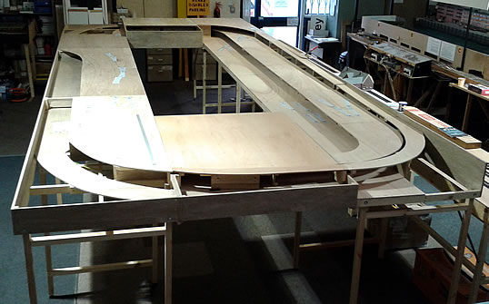
29 January 2014 – The baseboards have been built and are now installed in our club room. Wiring buses have been pre-installed, so the next stage is to lay track and get something running (at least a single circuit!) for members to run trains on. After this, we will progress to scenic works. It is hoped to offer members some form of modelling ‘master class’ session while the layout is being built in order for everybody who wishes to do so, to develop their skills as part of the process of construction.
The layout is being built on three levels; the lower level being for two continuous loops of DC operation while the middle level and branch line spur to the upper level will be DCC operated. More details will be added here as progress is made but for now, the diagram below shows how the layout is intended to go together.
- Blue = lower level (DC)
- Red = middle level (DCC)
- Purple – upper level branch line (DCC)
March 2014 – Late February saw work commence on the track laying for the DC section of the layout. To make this easier a number of the DCC boards have been removed to provide easier access to the lower DC level.
The actual laying of the track has progressed extremely well and the DC track work is complete. The following gallery of pictures shows the DC track.
During the track laying, a problem with the original design was found, this was the fact that plan required a four track tunnel portal which could not happen in reality. Therefore, the tracks at the front of the layout have been laid with a wider centre gap to allow for two double track tunnels staggered with a connecting retaining wall.
The DC track has a number of isolating sections which have been temporarily wired to directly to the controller to allow for the testing of the DC layout.
8th August 2014
The DC track has been well and truly tested with members running many different locos with no problems encountered. The entire track has been painted and ballasted and now just needs to have the wiring and point motors added.
It was planned that at this point the baseboards would have been split and the wiring and point motors installed. However, to allow members to continue to run trains it was decided to lay the DCC track before dismantling the baseboards.
The DCC track laying progressed very well and a major milestone has been reached this month with the track laying being completed (except for the engine shed lines). At this point only part of the gradient to the upper terminus station has been laid, but the track on the terminus will be laid as phase three of the project.
The plan for the forthcoming weeks is –
- Add dropper wires to each piece of track.
- As it has been decided to isolate the frogs on the points, the dropper from the point will be temporarily connected to the piece of track after the point. This will provide electrical continuity for testing of the DCC layout.
- The DCC track will then be connected to the Hornby Elite controller.
- The track will then be turned over to the members for testing.
Then –
- Resolve any problems encountered during testing.
- Paint and ballast all of the exposed track work.
- Split the baseboards to complete the wiring and installation of the point motors on both the DC and DCC layouts.
The following pictures show the progress made to the layout.
22nd August 2014
A major milestone has been reached and we have live running on the DCC layout. All of the track dropper wires have been added and these have been temporarily joined together to provide power to the complete track.
March 2015
The wiring of the layout started back in November 2014 and it was planned that it would take about 8 weeks to complete.
Well, a massive 20 weeks later the wiring is completed. Each of the boards (8 boards in total) has been wired, both for the DC (analogue) layout and the DCC layout. Point motors on both the DC and DCC sides have been affixed and wired.
It is estimated that we have used approximately 350 metres of wire, 1000 cable clips, 31 points, 46 plugs or sockets and 15 metres of cable wrap.
Each board was individually tested and then tested in conjunction with is neighbor. As part of this exercise toggle clamps where also added to each board joint to make the erection and dismantling of the layout easier. Once the layout has been put back together final acceptance testing will be carried out.
The next phase will be to add the terminus station and at the same time the scenery crew will start the process of making the layout look like a railway.